| Case Study: GFI and ACI Tripping | |
|---|---|
Description: This project is documented in our portfolio here. Soon after the client moved into the new home, GFI breakers, GFI receptacles and ACI breakers started tripping randomly. |
|
At first there appeared to be no pattern but it may be that the problems are occurring during periods of generator run. At this time the 30 kVA generator is charging a substantial battery array through three Outback Radian GVC8048A inverters. |
|
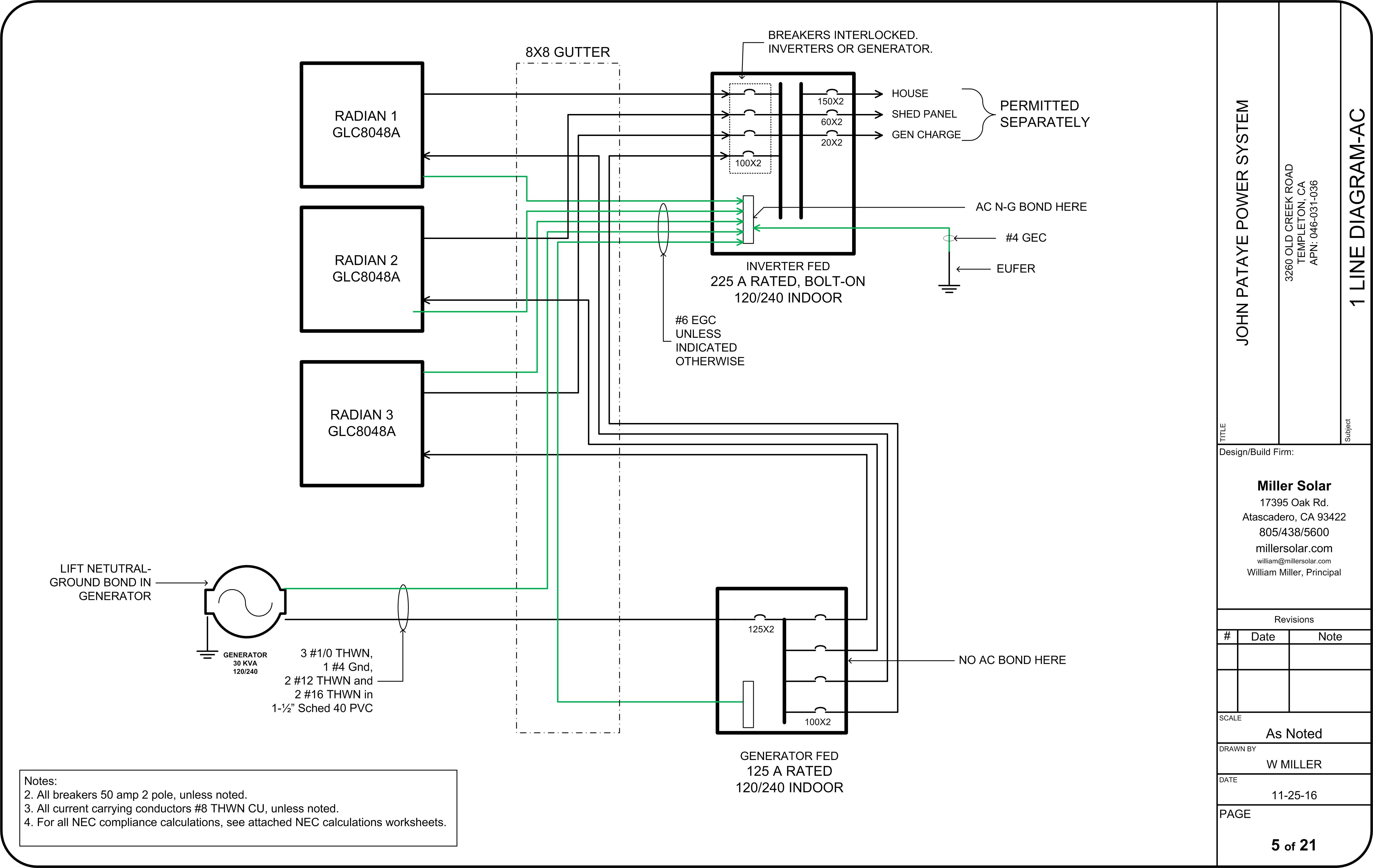
The first thing to check in a scenario such as this is the AC neutral to ground bond. This is done at one point only, in the Inverter Fed panel. This panel service as the primary power source to this off-grid installation. See this link for an AC block diagram. |
|
The second thing to check is the efficacy of the AC grounding electrode. A resistance measurement was made between the primary GEC and a secondary GEC some distance away and it indicates a resistance of 0.06 ohms. This is considered quite good. |
|
In the process of troubleshooting this problem, it occurred that under certain circumstances inexpensive volt meters began reading significantly higher than true-RMS volt meters. This is an indication of high waveform distortion. |
|
Measurements of total harmonic distortion (THD) were taken with a Fluke VR1710 power quality recorder. The results were: Inverter only: 2.5% Gen Max: 19% Gen 5 Amps: 8% These readings are of the voltage waveform only. |
|
Observations were made of the effects of adding resistive loading to the generator. Lacking a real-time THD monitor, the relative presence of THD was observed with the delta between VAC using an inexpensive voltmeter as compared to a true-RMs meter. When the inverters were battery charging the symptoms of THD appeared to increase. |
|
A Fluke 43B meter was placed on order but when it arrived it was DOA. That meter is being returned and a replacement is being ordered. |
|
A plan for subsequent testing and experimentation is being formulated. Here are proposed tests: 1. Measure voltage waveform distortion and current waveform distortion separately. 2. Measure THD under charging with each inverter removed from the circuit. 3. Measure THD with individual inverter power module disabled (we have already experienced one defective power module). |
|
Update 01/29/2020: We revisited the site and tried using another generator, a Multiguip 45 kW portable diesel generator. The results were somewhat improved: 20%f voltage waveform THD instead of 28% with the stationary Kohler 30 kW propane unit. We also tried isolating the various individual inverters and power modules. No one component seems to be causing the extreme THD of the voltage waveform. Measurements are now being made with a rental Fluke 435 Power Quality Monitor. |
|
Update 02/10/2020: We had suggested to Outback engineering that we might try different AC input modes. We were told this would not make any difference. Outback re-thought the answer and suggested we try the Backup AC input mode. We tried this mode, along with UPS and Support and voila: All three of these modes exhibited remarkably reduced THD, in the range of 3.5%f on the voltage waveform. UPS mode is inefficient and we were told that the Support mode is problematic for stacked inverters, so we left the system in Backup mode. Over the last few days no GFI or AFCI breakers or devices have tripped. The explanation we received for this phenomena is that the Generator mode utilizes a "diode charging" circuit design while the other modes use a different configuration. We are not real clear on the intricacies, but we will not argue with success. |
|
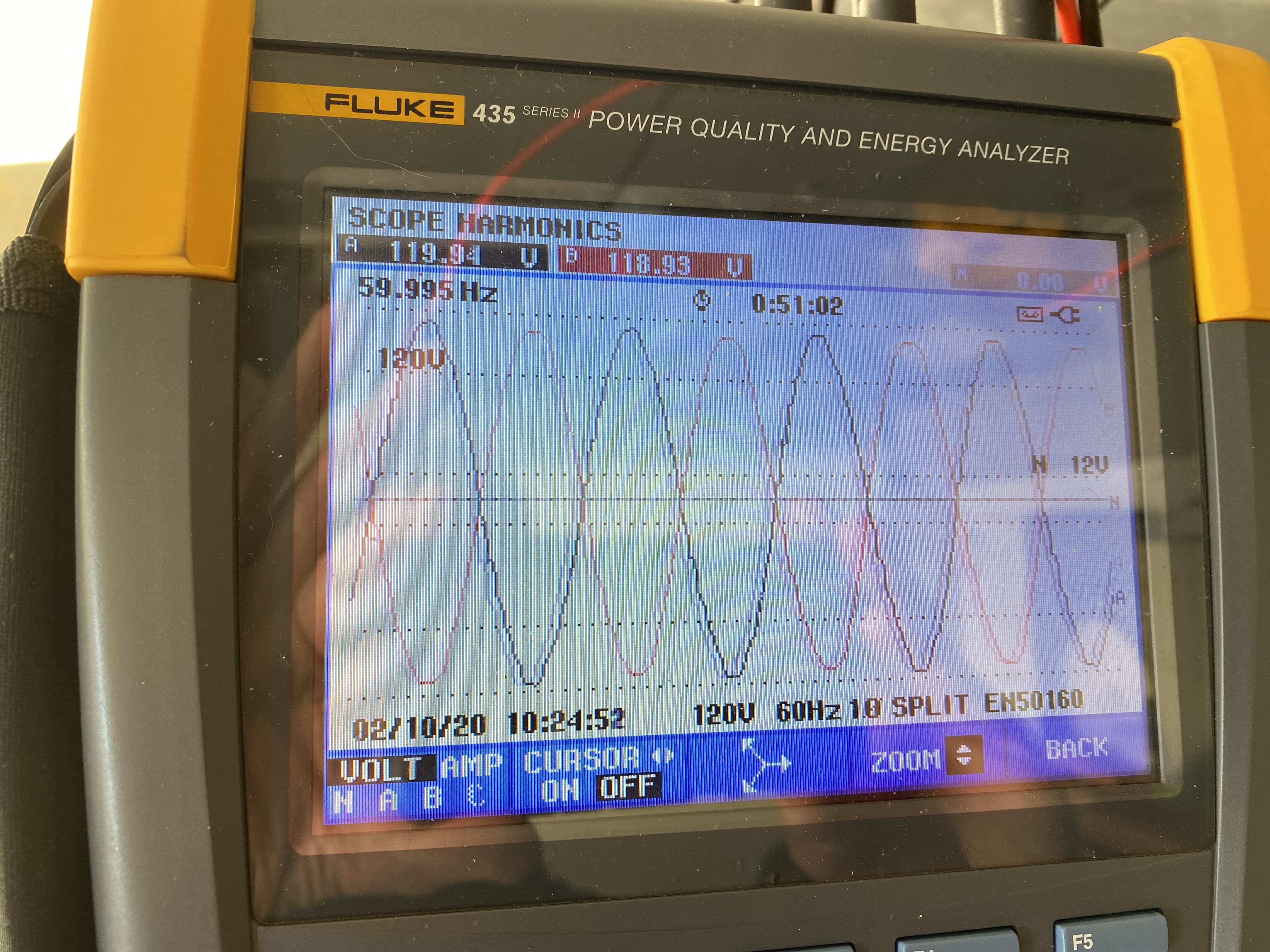
Below are a few photos of the AC waveforms: |
|
 |
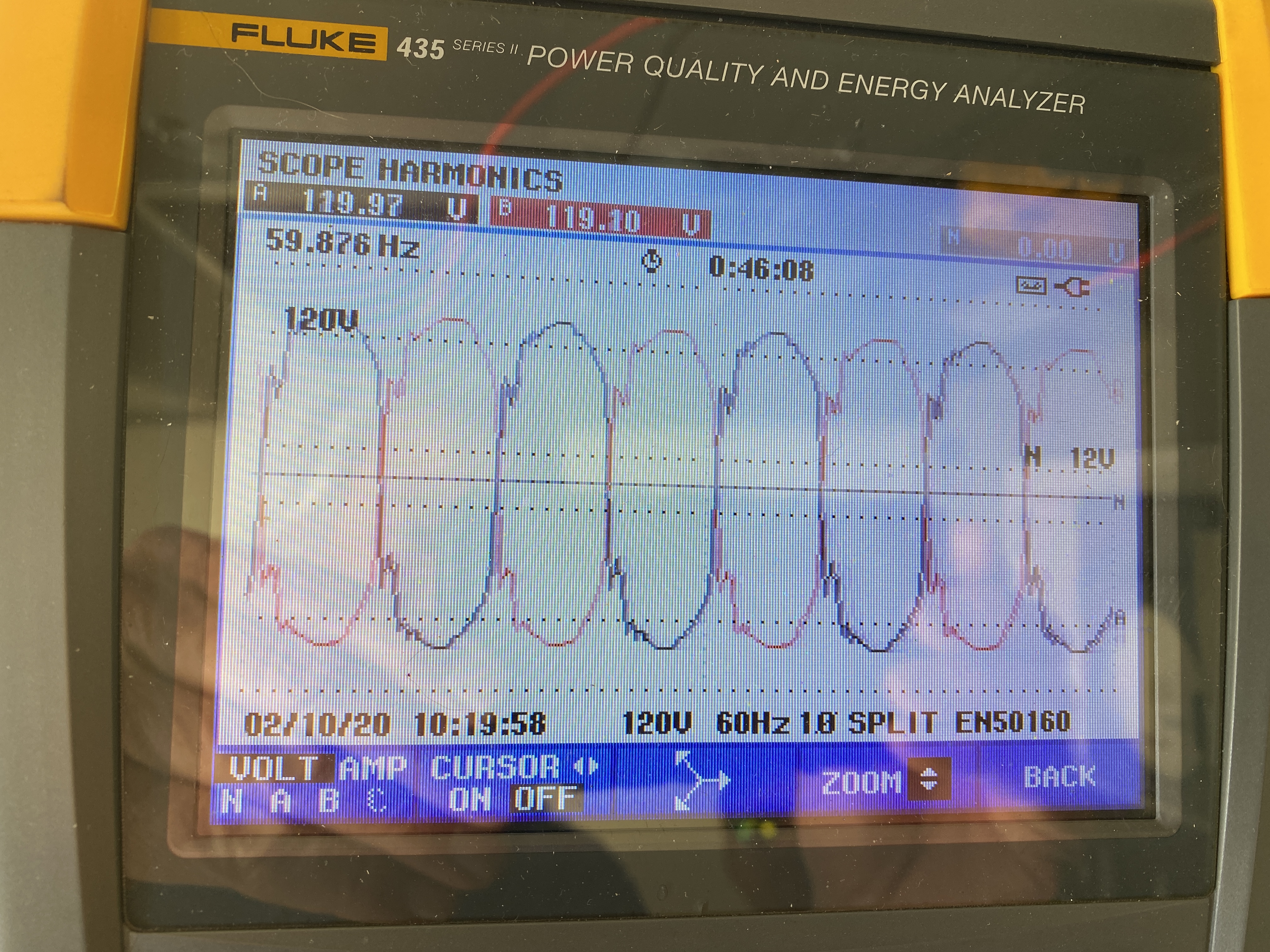 |
3.5%f THD waveform. |
28%f THD waveform |